The meridional shape, number of blades and component specific work rVt (ie. impeller head) were loaded from TURBOdesign Pre into TURBOdesign1 for the detailed 3D design of the pump impeller and diffuser. TURBOdesign1 is unique blade design software that uses the 3D Inverse Design approach to compute the blade shape for a given blade loading distribution.
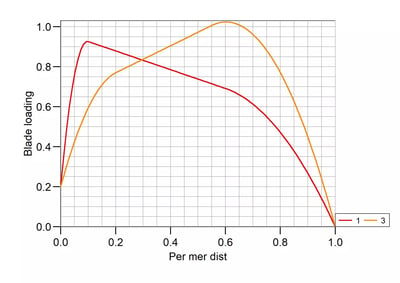
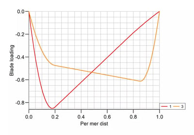
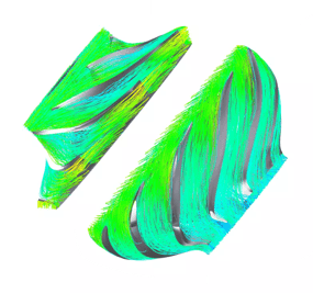
A number of design iterations were performed directly in TURBOdesign1 with the help of the 3D inviscid flow solution and performance data provided by the code to fine tune the meridional shape and blade loading, before assessing the impeller performance via 3D CFD. The initial design loop in TURBOdesign1 taking less than 30 seconds per design iteration, it ensures large areas of the design space are covered with minimal number of CFD iterations, making it possible to achieve breakthrough designs without increasing product development costs.
The design of the leakage gaps and the balancing holes was performed looking for a trade –off between reduced axial thrust, below the limit requested by the customer, and low leakage and disk friction loss. Leakage flow carries the angular momentum into the impeller sidewall gaps and thus enhances fluid rotation which causes disk friction, on the other hand pressure losses along the sidewall gaps helps to reduce the amount of fluid leaked through the gaps. The sidewall gaps were then shaped based on these considerations, looking for the right compromise between disk friction losses and leakage losses.
Balancing holes diameter were designed as result of an iterative approach looking for a configuration which can guarantee axial thrust below the requested value while ensuring low losses due to the flow disturbance caused by the presence of the holes.
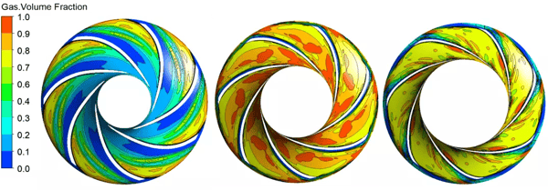
The gas handling capabilities of the pump was also analysed using multi-phase flow simulations. Results demonstrate good gas handling capabilities of the pump and no gas lock was experienced up to 60% GFV. Results highlight the formation of a gas pocket, yet no segregated flow was individuated.