The first phase of the project was the analysis of the existing impeller and inlet component. The analysis allowed for extracting the flow field at the operating point and validating the model used for the analysis of the inducer in the design phase. To design the inducer it was necessary to build the impeller characteristic and assess the suction performance of the impeller alone. This was used to design the inducer and determine the pressure rise (or Euler head) necessary in the inducer to avoid operating under cavitating conditions.
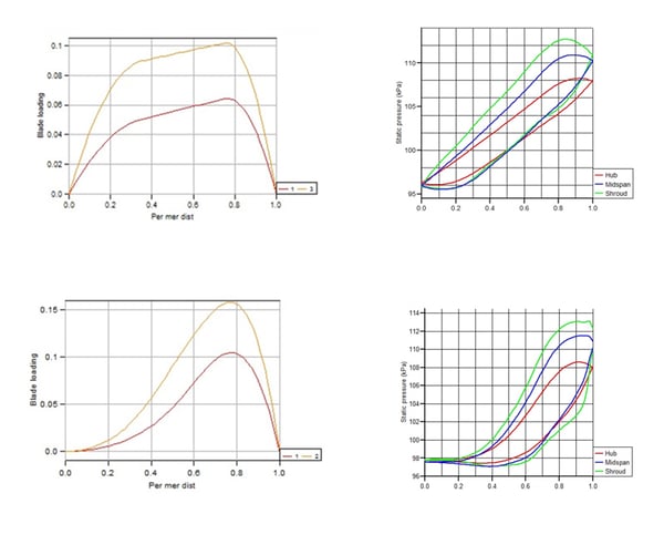
The design of the inducer was done using the 3D Inverse Design software, TURBOdesign1. The inlet condition was simplified (linear distribution) from the flow field data extracted from the analysis phase. The meridional shape of the inducer was created taking into account the geometrical constraints fixed by the first stage pump impeller. The spline features for the blade loading were used to customize the loading for optimum loading repartition without cavitation. Quick iterations were done by changing the blade loading and looking at the static pressure from the inviscid flow solution produced by TURBOdesign1. It identified an optimum loading to increase the pressure gradually within the space constraints.
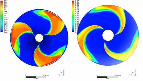
A multiphase CFD analysis was then performed to assess the suction performance at design flow (100%Q) and high flow (130%Q). The head breakdown was constructed for the two flow conditions and the flow field was then analyzed to spot areas of improvement (Fig. 2).
The loading spline was then modified in order to further delay the formation of air bubbles, which cause a drop in performance and can potentially cause vibration and damage to the pump.
As the Euler head was fixed by the work coefficient (rVt*) during the designs iterations, only the loading distribution and meridional shape were used to improve the suction performance.
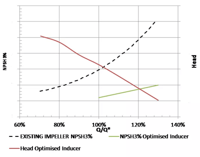
Eventually, an inducer design was created that could fit the geometrical constraints, match the impeller design and improve the suction performance of the stage. A reduction of the NPSH3% was observed and the inducer halved the NPSH3% of the first impeller stage at design point.