
The customer, one of the leading manufacturers of turbodrills for the oil and gas services market, asked ADT to carry out the complete redesign of their existing hydraulic drilling turbine to suit different types of rock formations with a single design.
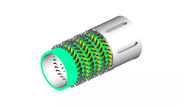
Turbodrills, multistage axial turbines with rotor and stator configuration that can have as many as 150 stages, are used for specific applications in oil and gas drilling - they use the fluid required to clean the borehole to drive a turbine to turn the drill bit. Conventional turbines run at relatively high speeds / low torques, which limits their applications to specific rock types.
The performance targets set by the customer for this project therefore requested an increase in torque at the low operating speeds, and a low runaway (zero-torque) speed to ensure safety of the drill-line and surrounding components.
The overall sizing of the turbine being fixed by the requirement to fit within fixed borehole sizes, ADT investigated various possible meridional, including repeating mixed-flow designs, to evaluate the potential for achieving high torque with low runaway speeds but unfortunately the results showed that any conventional design could not meet the target requirements and novel avenues needed to be explored.

ADT used the 3D Inverse Design code TURBOdesign1 to design a number of rotor / stator configurations with varying design flow, rpm and meridional channels to understand the design parameters that most influenced the slope of the torque characteristic curve.

Very careful control of the blade loading using TURBOdesign1’s inverse design methodology allowed the flow to remain stable at low rpm producing high torque, while inducing a controlled separation at high rpm in a way which reduced the torque obtained without any other adverse impacts to the turbodrill such as vibrations or blade erosion.
The final design provided 30% more torque at low rpm, whilst simultaneously reducing runaway speed by 10%.
The final phase of this design project included using automatic optimization to improve the stage efficiency. The blade geometry in TURBOdesign1 is parameterised by using the blade loading and TURBOdesign Optima is used to run Multi Objective Genetic Algorithm (MOGA) to explore the design space and create a pareto front of contrasting design objectives.
TURBOdesign1 parametrises a fully 3D blade shape with only a few design parameters and also provides detailed 3D inviscid surface pressure and velocity information, using ADT’s correlations based on the 3D inviscid flow fields it is possible to run hundreds of designs in less than one hour and achieve a well-defined Pareto Front (Fig. 4 and 5) clearly showing the trade-off between loss mechanisms.


The turbine stator and rotor blades were parameterised using 8 blade loading parameters and also including the number of blades, the optimization objectives were to minimise the profile losses and diffusion ratio for the stator and secondary flows and diffusion ratio while maintaining profile losses below the baseline blade for the rotor. The resulting Pareto Fronts are shown in Fig. 4 and 5 for the Stator and Rotor respectively.
