Design Targets
The project involves the design of a two-stage centrifugal compressor for chiller application. The refrigerant adopted is R1224yd(Z), which is a non-flammable (ASHRAE A1), low pressure, low GWP (under 1) refrigerant newly developed for chiller and heat pump applications. The capacity requirements include three operating modes: frequent operation, over load and low load operation. The compressor design aims to cover these operating points with different pressure ratio and under different massflow rate.
Deliverables
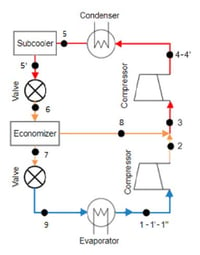
Detailed design of the two stage back-back compressor including the interconnection pipe that achieves high COP at frequent operation point and meets the off-design operation requirements.
Impact
A 2 stage back-back compressor design using a novel low GWP refrigerant that achieves high COP at frequent operation point but at the same time meets the low load and high load conditions.
The design of the compressor aims to cover a wide operation range. A ‘back-to-back’ configuration is therefore selected considering its advantage on performance range. Each stage of the compressor includes an impeller and a vaneless diffuser with a downstream volute. The operating point with maximum capacity and pressure ratio will determine the maximum power needed from the motor. Both the shrouded and unshrouded impeller have been evaluated to provide information for rotor dynamics study and motor design.
Initial Cycle Analysis and Stage Sizing
TURBOdesign Pre was used to investigate the choice of design point, rotational speed selection and the pressure ratio split between the 1st and 2nd compressor stage. Both the cycle analysis and the compressor dimension/performance are available using the cycle/meanline coupled simulation. A preliminary performance map prediction was also provided by TURBOdesign Pre analysis. Based on a parametric study the design flow rate and RPM were selected and the optimum pressure ratio split between 1st and 2nd stage was determined.
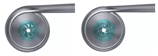
TURBOdesign1 was used to design an initial first and 2nd stage impeller with full blade (no splitters). Through CFD evaluation the key aspects of the impeller design that impact manufacturing requirements such as power consumption and axial thrust were confirmed. An unshrouded impeller was used for the study because of manufacturing requirements.
3D Design and Optimization of Compressor Stage
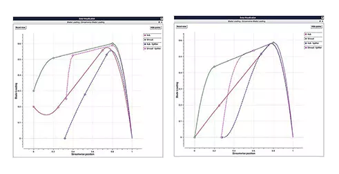
In order to meet the wide operating range requirements splitter blades were used for the final design. TURBOdesign1, by specifying the loading distribution for the full and splitter blade independently can design high efficiency impellers with splitter blades which don’t necessary have the same shape as full blade. Therefore, the blade surface pressure distribution can be controlled by using the aerodynamic inputs, in comparison to the conventional design methods where blade angles and camber line profile are specified in a trial-error practise and where the splitter blade are generally placed at mid-pitch location and have the same geometry as the full blade. The commercial CFD code (ANSYS CFX) was used to verify the performance of the impeller under various operating conditions. For the 2nd stage inlet conditions, some pipe loss was assumed. Some design iterations were carried out to meet the high-capacity requirement.
Following the aerodynamic design, the FEA and modal analysis were conducted on the impeller structure. TURBO design Volute was used to design the volutes for each stage.
Performance Prediction for Two-Stages Compressor
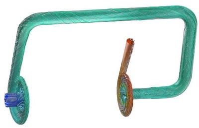
After the initial compressor stage sizing, the interconnection pipe design was carried out. It was designed to connect the 1st and 2nd stage compressor with three elbows. A CFD model that combined the 1st and 2nd stage compressor was then created to evaluate the overall performance of the two-stages compressors. A performance map of 5 different rpms was generated.
.jpg?width=400&name=Fig.%204.%20Relative%20Mach%20Number%20Contour%20at%2050%25%20Span%20(left%2c%201st%20impeller%3B%20right%2c%202nd%20impeller).jpg)
Conclusion
The two stage compressor stage using the low GWP refrigerant met the targets on high COP at frequent operating points while meeting the high and low load requirements.