Design Targets
The scope of this project is to design a 2-stage inline chiller compressor for HVAC application. The refrigerant adopted is R1234ze(E), which is a low GWP (~6) alternative to R134a. High-efficiency level is required in a range of flow rates (20% around design condition).
Deliverables
Design of a 2 stage inline compressor that achieves high COP at most frequent operating points but also meets the partload conditions.
Impact
A 2 stage high efficiency inline compressor with specially designed tandem return channel to be used as inlet guide vane for the second stage compressor.
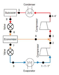
The customer, one of the world’s leading HVAC manufacturers, required the design of a new range of chillers using R1234ze(E) refrigerant. The chiller uses a 2-stage in-line compressor. Both compressors and the return channel need to be designed.
Initial Cycle Analysis and Stage Sizing
TURBOdesign Pre (refrigeration cycle coupled with compressor meanline design) was used for the initial cycle analysis and compressor stage sizing. Both the cycle and the compressor performance were available from the simulation results. The compressor map could also be produced to evaluate the operating range. A parametric study was carried out to find the optimum rpm and pressure ratio split between 1st and 2nd stage compressor. Based on the customer’s feedback from rotor dynamics, a proper design rpm was chosen to balance the requirement from aerodynamic performance and mechanical integrity.
3D Design and Optimization of Compressor Stage
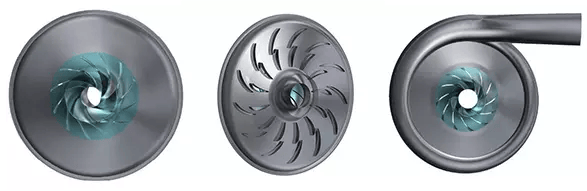
In the detailed 3D blading design, the 1st stage impeller was generated with full blade and splitter blade.
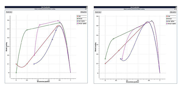
Using the 3D blade inverse design software TURBOdesign1 the full and splitter blade can be obtained by prescribing the blade loading distribution. Therefore, the blade surface pressure distribution can be controlled by using the aerodynamic inputs, in comparison to the conventional design methods where blade angles and camber line profile are specified in a trial-error practise.
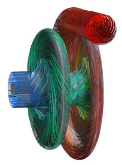
The impeller performance was verified by using commercial CFD code (ANSYS CFX). Design optimization was carried out to achieve good efficiency level at a range of flowrate. The downstream return channel was then also designed using TURBOdesign1. The return channel vane has tandem blade so that the flow can be better controlled. There is also injection flow from economizer into the return channel. TURBOdesign1 has a unique capability to design high performance rotating or stationary blade with tandem configuration.
The injection hole size and position were carefully designed based on the flow field inside the return channel. The 2nd stage impeller was designed in the same way as the 1st stage. It also has a full blade and a splitter blade. But the inlet condition was taken from the return channel outlet flow. The 2nd stage was also optimized to have good efficiency at a range of flowrates. FEA analysis were conducted on both the 1st and 2nd impeller structure, which showed the stress on the blade were manageable.
Finally, the downstream volute was designed using TURBOdesign Volute. It can automatically produce a volute area distribution that matches well with the vaneless diffuser exit velocities. A smooth volute tongue was generated at the same time. The overall performance of the two-stage inline compressor was evaluated in an assembly CFD model. The results showed the efficiency curve is rather flat over a range of operating conditions, which means good efficiency is achieved at different flow rates.
.jpg?width=400&name=Fig.%204.%20Relative%20Mach%20Number%20Contour%20at%2050%25%20Span%20(left%2c%201st%20impeller%3B%20right%2c%202nd%20impeller).jpg)
Conclusion
The resulting stage met the main targets in terms of wide operating range. Also the flat efficiency characteristics of the two stage inline compressor ensured high COP over a wide range of conditions and very high values of IPLV.