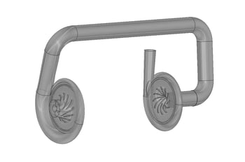
The customer, one of the world’s leading suppliers for HVAC industry, required the design of the compressor for an upgraded range of chillers using a new refrigerant R1234ZE. The new refrigerant has low Global Warming Potential (GWP ~ 6), and is used as a replacement for R134a. It is classified as A2L (low flammability and low toxicity) under ASHRAE classification. The chiller compressor takes a 2-stage back-to-back layout to achieve a good performance at both design and off-design conditions. An economized flow was injected in-between the two stages.
The design targets included four rating conditions and the maximum lift condition. Both COP and IPLV were desired to be competitive for a small tonnage chiller. The maximum (choking) capacity had to be achieved within the maximum rotational speed provided by the customer.
TURBOdesign Pre was used to assess the performance potential of different stage pressure ratio split, different RPMs, shrouded or open impeller etc. A preliminary performance map prediction was also provided by TURBOdesign Pre analysis. Based on these the design RPM was selected and the optimum compromise betewen stage.

A shrouded blade was chosen over an open impeller for the advantage on efficiency, which was also compatible with the customer’s manufacturability. During the meanline analysis phase, it also appeared that a splitter blade design could be necessary to reach the maximum capacity requirement.performance and overall operational range was determined.
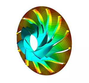
By using the 3D blade Inverse Design software TURBOdesign1 with a simple blade loading an initial (full blade) impeller design was obtained to achieve the target pressure ratio and the maximum capacity at high RPM. The design was also modified to have a good compressor efficiency at 100% load COP evaluation. Following this initial design, an optimized design with the splitter blade was generated. Both the meridional profile and the blade loading distribution were optimized during the detailed design process. For the second stage inlet condition estimation, certain pipe loss was assumed and provided by the customer. Each stage compressor was designed to have a large operating range at design RPM. The other rating conditions or IPLV can be covered by varying the rotational speed and closing the IGV.
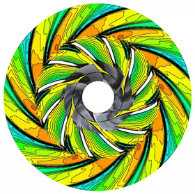
The optimized design was analysed using the commercial CFD code (Ansys CFX) across its operating range. The numerical prediction showed good efficiency levels at both design and off-design conditions. The performance at various RPMs were also checked against the targets. The analysis showed that with the help of IGV the compressor design can deliver reasonably good efficiency at load conditions. The maximum lift condition was also investigated numerically.
The required RPM and the pressure ratio split between the two stages for this condition was predicted. Meanwhile, the mechanical stress level on the blade was checked by FEA study. Some iterations were carried out between the aerodynamic design and the stress analysis. The blade thickness profile and the blade number were modified to reduce the stress level while maintaining the choke margin. The maximum stress at overspeed of the final design was controlled within the material limit. Furthermore, the power consumption for each compressor stage was extracted from the CFD analysis at the maximum lift condition and the near choke condition.
TURBOdesign Volute was used to generate the volue design for both the two stages.
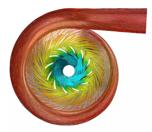
TURBOdesign Volute automatically produces a volute area distribution that matches well with the vaneless diffuser exit velocities. A smooth volute tongue could be produced at the same time. The performance of the volute was verified by CFD analysis together with the impeller and vaneless diffuser at various flow rate conditions. No reverse flow was observed at the lowest RPM and flow rate. Both the two stages’ performance showed good efficiency and operational range.