The customer, one of the leading suppliers for aerospace companies, asked ADT to carry out the complete aerodynamic design of a radial inflow turbine stage using inverse design approach available through the TURBOdesign Suite software. The turbine is to be used for expanding air to drop its temperature to very low value for a high altitude testing.
The turbine had to be point designed to deliver the right mass flow at right temperature for the given pressure ratio with a limited power delivery. The rated rotational speed is also specified. This represents a closed set of performance constraints.
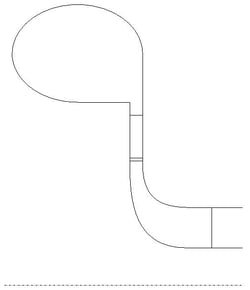
The design of all the three turbine stage components (inlet volute, stator vane and centrifugal impeller) was performed using TURBOdesign Suite. The preliminary design of the turbine was performed using 1D sizing software TURBOdesign PRE. A 1D design meeting the power with the required exit temperature is obtained. The meridional geometry, blade number and other design inputs required for the blade design software TURBOdesign 1 is provided by TURBOdesign Pre.
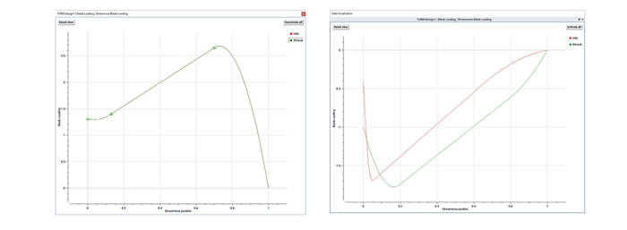
An aft loaded nozzle blade has lesser profile losses and thus losses. For a 2D blade, both hub and shroud loading used are identical. A fore loaded hub is to be used for an RIT due to its nature and shroud loading is arrived at based on getting a better flow incidence.
The stator vanes and rotor blades are designed using the inverse blade design software TURBOdesign 1. The inverse design approach ensured that the performance requirements are met with in a couple of design iterations. Even though each component is designed separately, TURBOdesign1 ensured proper matching between the components since it uses the outflow conditions of each component as the inflow boundary conditions for the following one. The matched blade angle of the components made the flow well aligned in the downstream components.
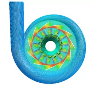
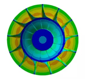
Inlet volute is designed using TURBOdesign Volute which is also an inverse design software. This inverse design approach produced a properly sized volute for the turbine. Fig. 1. above shows the streamlines through the turbine.
CFD analysis of the final design showed that the required mass flow, temperature and power specifications are met. FEA analysis carried out for the rotor blade showed that the maximum stresses in the blade are within allowable stresses for the selected material. Fig. 4. below shows the stress distribution in the impeller. Finally, a CFD based performance map for the turbine stage is produced for 4 different operating speeds.