
Johnson Controls are a global manufacturer of heating, ventilating, air-conditioning and refrigeration products. They manufacture heating, air-conditioning and thermal-storage equipment for universities, hospitals, office buildings, airports, marine vessels and residences. They also manufacture refrigeration and gas-compression equipment for processing food, beverages, chemicals and petrochemicals.

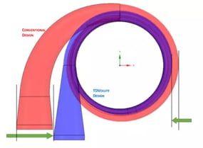
Johnson Controls’ YORK© centrifugal compressors are heavy duty and in use in many large, well-known buildings across the world. Johnson Controls used TURBOdesign Volute to redesign and optimize the volute for the YORK© centrifugal compressor. The design of a centrifugal compressor for industrial cooling applications faces two main challenges: high aerodynamic efficiency and compact packaging. TURBOdesign Volute was able to meet these challenges and generated a reduction in overall size of 8% and improved head and efficiency at the design point of 0.8% and 0.4% respectively, when compared to the existing design.
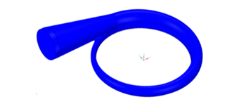
The reduction in size was generated by switching from a circular cross-section to an elliptical one, combined with a change in volute cross-sectional areas of distribution and different packaging. The optimum area distribution was obtained as a result of several design/analysis iterations and the main target of the area re-distribution was compressor efficiency. This is where TURBOdesign Volute offered the main advantage of outputting a 3D model of the volute that could be sent to a meshing software in a couple of steps. The entire process, from new inputs to TURBOdesign Volute to solid model took less than 15 minutes. Figure 1 shows an example of a 3D volute ready for meshing. As a result, an optimized volute could be generated in a day. By comparison, using the older methodology and creating the solid model from ground-up took several days per design iteration.
A better cross-sectional area distribution, combined with a straight volute discharge diffuser and a better packaging around the tongue, resulted in almost no flow separation at volute outlet and higher pressure rise. This led to 0.4% increase in efficiency and 0.8% increase in the head at the same inlet conditions. Moreover, the amount of pressure recovery needed in the conical discharge section of the volute was less, which allowed for smaller overall volute design.
For Johnson Controls, another useful feature of TURBOdesign Volute was the ability to restrict the minimum cross-sectional area. Even though this was a departure from optimum design for efficiency, it was a hard constraint set by manufacturing technique. For large capacity compressors, this component is sand cast and there is a minimum opening needed for casting core insertion/extraction.
In centrifugal compressor design, the volute (or scroll collector) is often treated with less consideration than the upstream components; the impeller and diffuser. Its design is far less complex than the blade region of the impeller or vaned region of the diffuser. The outer component of the centrifugal compressor is sometimes subjected to strict geometrical constraints. Whilst simultaneously carrying a significant impact on overall performance.
The traditional volute design relies on picking a cross-sectional shape and a cross-sectional area distribution that is typically linear or parabolic, which satisfies the law of conservation of angular momentum and mass. This methodology assumes no circumferential variation of aerodynamic and thermodynamic parameters at the volute inlet (diffuser outlet). Once this cross-sectional area distribution is established, the 3D models need to be created, using a fixed number of 2D cross-sections which are then blended together in 3D shape. This is a time-consuming process and also leads to a great degree of subjectivity for the designer.
.webp?width=400&name=AnyConv.com__Pressure%20colored%20streamlines%20in%20the%20two%20volutes%20(conventional%20design%20vs.%20new%20design).webp)