
At the present time, Stepanoff’s design methodology based on empiricism using an experimental database is still widely used in pump design. This design is so popular because based on his experimental investigation of the correlations between many design parameters and pump performance he “strongly suggested” that the optimum blade exit angle was 2β = 22.5 degrees. It is true that designers using Stepanoff’s method can design pumps that demonstrate moderate performance with very cheap design costs. These facts along with a rich experimental database make this method attractive as a standard design methodology. However, it is also true that Stepanoff’s method can not be applied to breakthrough designs beyond the design range he originally tested.
%20(1).webp?width=350&name=AnyConv.com__Fig1%20(1)%20(1).webp)
By using TURBOdesign1 in the design of a rocket pump, JAXA (the Japan Aerospace Exploration Agency) have been trying to overcome “Stepanoff’s Spell” (2β = 22.5 degrees) on pump design. A compact design intended to minimize weight is advantageous in any kind of machine. For many years, rotating machinery which operates at higher speeds and is compact in size is also being developed.
JAXA aimed to design a centrifugal pump which achieved high energy density (achieving the same head and flow rate with a compact size pump under the same rotational speed as the original) in order to reduce the weight and cost of the rocket turbopump (fig. 1). The target size in this investigation was a 10% smaller diameter at the diffuser exit than the conventional pump designed by Stepanoff’s method (2β = 22.5 degrees). The impeller and diffuser become highly loaded in a compact design resulting in a mixing loss downstream of the impeller. This tends to increase by highly non-uniform flow with developed jet / wake flow at the impeller exit. Therefore, the designer should take care to define the blade loading distribution in order to control internal flows in the impeller.
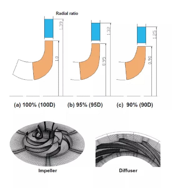
JAXA has applied TURBOdesign1 to investigate the compact turbopump design shown in Fig.2 by controlling the blade loading of the impeller.
The effect on the pump performance of pressure recovery in the diffuser vane is larger for a low specific speed pump. Therefore, the blade loading of the diffuser is also controlled by TURBOdesign1.
.webp?width=600&name=AnyConv.com__Fig3%20(3).webp)
A parametric study of the diffuser loading distribution by CFD, as shown in fig.3, demonstrates the advantages of a fore-loaded diffuser for diffuser performance. This study indicates that the pressure rise should be accomplished in the front part of the diffuser rather than in the rear part. This is because the effect of flow separation is larger in the rear part of the diffuser vane.
The effect of the compact design on the diffuser performance was analysed by using CFD, as shown in fig.4. In this design, each diffuser was designed using the front-loaded loading distribution as shown in fig.3. The diffuser exit absolute circumferential velocity was set the same as the original 100D diffuser. This result shows that the diffuser performance of the 90D diffuser dropped significantly at 94% design flow rate (m/md=0.94) caused by a large separation in the diffuser channel. In the case of the 95D diffuser, diffuser performance at m/md=0.94 is still compatible with the original 100D diffuser.
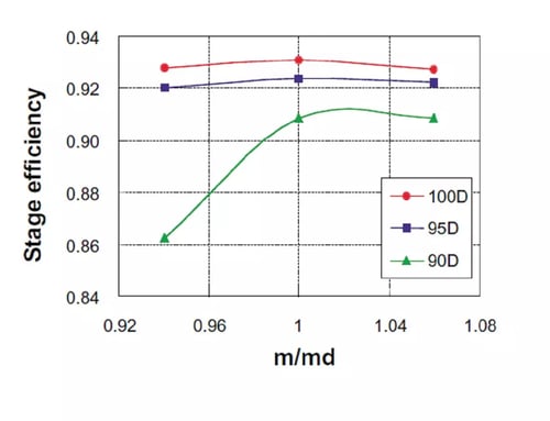
Fig.5 shows pump performance calculated by summing impeller and diffuser performance. This shows that pump performance for the 90D stage dropped significantly at m/md=0.94. In the case of the 95D compact pump, performance is only slightly lower than the original (100D) stage. However, by using TURBOdesign1 it should be possible to improve performance by optimising the impeller exit stacking shape and adopting a three dimensional diffuser design. In conclusion, it is possible to achieve a 95% compact design.