
Ebara Corporation are committed to becoming an environmentally aware enterprise and have adopted a corporate philosophy that stresses extensive contribution to society by providing superior technologies and services related to water, air and environment. The Fluid Machinery & Systems Company is the oldest of Ebara’s three business groups and boasts top-level technologies to world-class standards.
For many years, Ebara’s Fluid Machinery & Systems Company has provided pumps, fans, compressors, chillers and other machinery and related equipment which serve as the infrastructure of daily life and industry. To create products that are competitive and environment-friendly, the company continues to seek improvements in economic efficiency and reliability, and is developing progressive technologies aimed at ongoing improvements in energy efficiency, compactness, weight reduction and longevity.
Incorporating TURBOdesign1
Ebara has already established facilities for the development and fabrication of the new pumps, which enables the manufacture of hydraulic parts for custom-made pumps within a short period using CAD data. The system links to TURBOdesign1 in which the blade geometry is computed for a specified blade loading distribution and a performance prediction method by Computational Fluid Dynamics (CFD) code. The newly developed processes of the design and fabrication system for hydraulic parts of the pumps are constructed in the following stages.
In order to design the hydraulic parts of the pumps, TURBOdesign1 was introduced into the design system together with CFD. TURBOdesign1 has been applied to find the optimum blade geometry for various types of pumps such as bowl type diffuser pumps, volute pumps, multistage pumps and sewage pumps. For these types of pumps, the optimum design parameters that enable the highest efficiency, highest suction performance, smallest size, stall free characteristics, and limit load characteristics, have been established in a wide range of specific speeds.
3D Modelling System
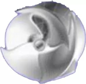
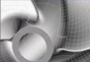
With regards to manufacturing, an original three dimensional CAD system has been developed for the three dimensional model geometry of the hydraulic parts. In this system, the three dimensional solid model can be formulated by the blade surface profile obtained by the inverse design method together with the preliminarily optimised meridional shape on the shroud and hub. Moreover, the fillets between the blade and shroud or hub surface can be automatically formulated. It becomes possible for the solid model data of the whole impeller as shown in Fig.1a & b to be prepared within a short period from the data file of the blade surface.
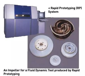
Rapid Prototype (RP) fabrication technology was applied to manufacture the model pumps. As for the fabrication of impellers, a Selective Laser Sintering system (SLS) apparatus was used to formulate a high strength glass nylon resin model. A Laser Stereotype Lithography (LSL) apparatus was used for the casing or diffuser model, as it permits to produce a large size epoxy resin model. The completed hydraulic models are set on a three dimensional Coordinate Measurement Machine, and its coordinates are automatically measured.
Hydraulic Model Test System
The fabricated hydraulic model is placed in an exclusive use performance testing apparatus, which can conduct the general performance test and reverse flow characteristic tests in full automated mode.
Fabrication of Hydraulic Parts for Production Pumps
The investment precision casting process using RP technology was also adopted for the fabrication of hydraulic parts for the production pumps. The RP system directly fabricates a lost form pattern for casting or indirectly a wax model via a master model, which is then applied to the investment precision casting process to produce the metallic hydraulic parts.
Unmanned Machining by Flexible Manufacturing System (FMS)
The hydraulic parts are machined by a flexible manufacturing system comprised of a 5-axis machining centre, a turning machining centre, an optical alignment unit, an automated transfer machine, an automated warehouse and a CNC machine.