CREMHyG is one of the world leading centres on research in hydraulic machines, especially turbopumps. It has been actively involved in the development of Ariane rockets by collaborating closely with SNECMA of France and Avio of Italy. CREMHyG has been using TURBOdesign1 for a number of years and in a recent project in the frame of student work at INP Grenoble University.
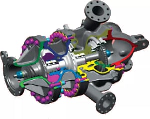
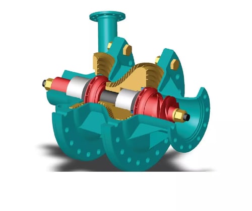
The code was used to design a generic turbopump inspired from the second stage Vinci H2 turbopump (Fig.1). An outline view of the components of the Vinci turbopump is shown in Fig. 1. The pump rotates at 90,000 rpm with a flow rate of 5.8 kg/s and pressure rise of 230 bar. It should be noted that the components designed under TURBOdesign are original and without reference of the real industrial one. It consists of an inducer, impeller1, return channel 1, impeller 2 and return channel 2.
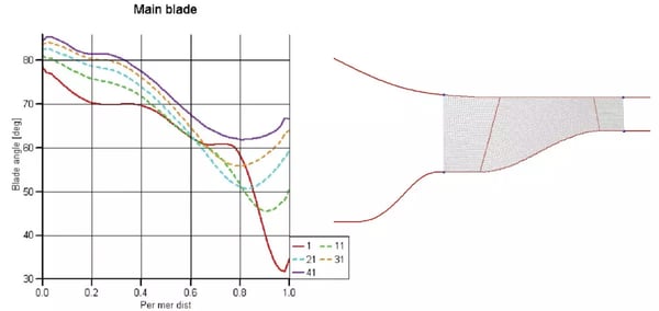
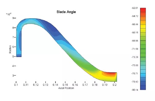
The objective was to develop an arrangement with inducer and two identical centrifugal runners. To adapt the static components (return channel and outlet diffuser) to rotor blade angles (inducer and both runners), all components are designed taking into account velocity field and pressure computed by TURBOdesign1 and incidence margin at leading edge. The first component designed was the inducer, to rise the pressure up to 20bar. The meridional geometry used for the design of the inducer is shown in Fig. 2 as well as the resulting blade angle.
The design was monitored for cavitation and it generally met the requirement for cavitation margin apart from a small region near the shroud leading edge region. The impeller 1 was then designed to give a pressure rise of 60 bar and again good cavitation margin was obtained in the design.
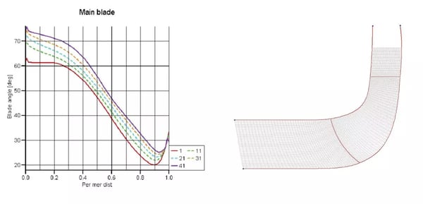
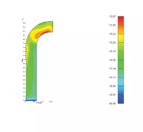
Finally the contours of blade angle for return channel 1 and 2 are presented in Fig 4 (a) and (b) respectively. The return channel 1 is very complex with the meridional geometry of the vane changing from radial at inlet to axial at exit, as shown in Fig. 4a. Despite its complexity TURBOdesign1 had no problem in the design of this component. This is also true of return channel 2.
The final 3D geometries of all the components designed by TURBOdesign1 are shown below.