
Blade lean is commonly used in the design of axial turbine nozzles to reduce endwall losses and to obtain a more uniform exit flow distribution. Numerical and experimental investigations have shown that the use of blade lean, whether straight or curved, in the conventional design practice merely redistributes the losses in the blade and does not result in a reduction in loss.
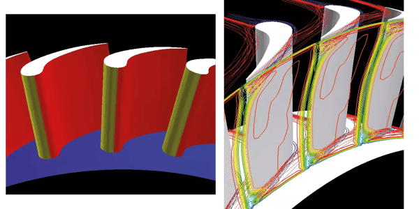
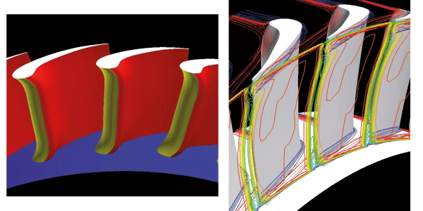
This is partly because in conventional design the blade profile is kept the same and the stacking line is changed to achieve the blade lean. This can adversely affect the blade circulation distribution. In TURBOdesign1 the blade profile is computed for a specified blade loading (and therefore circulation) distribution together with a specified thickness distribution and stacking condition.
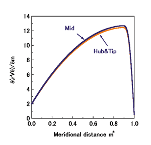
So the designer can change the blade stacking without any adverse effect on the blade circulation, as this is kept fixed. In order to demonstrate this fact, the blade loading shown in fig. 3. above, was used to design a nozzle. In the first instance radial stacking was used and the resulting blade geometry is shown in fig. 1. While keeping the same blade loading and thickness distributions the stacking condition was changed at both endwalls to reduce secondary flows. The resulting blade geometry computed by TURBOdesign1 can be seen in fig. 2.
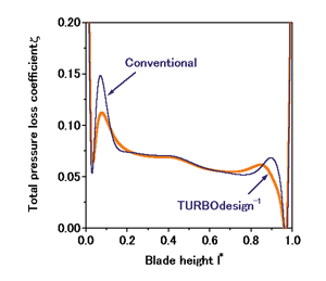
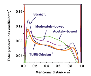
It is clear from fig. 4. that endwall stacking has resulted in appreciable reduction in endwall losses. However, more significantly, the nozzle with endwall stacking shows a reduction in overall stagnation pressure loss. This is in contrast to the effect of blade lean in conventional design practice (see fig. 5.), where blade lean merely redistributes the losses without resulting in any significant reduction in overall losses.
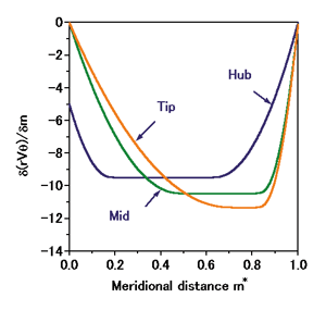
In the case of axial turbine rotor it is less common to use blade lean to influence the flow field because of structural considerations. However, by using TURBOdesign1, a designer can easily control the three-dimensional flow field by specifying the appropriate blade loading distributions. An example of a blade loading distribution used in the design of the rotor is shown in fig. 6. Using this distribution the rotor blade geometry shown in fig. 7. was obtained.
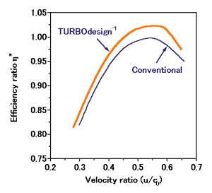
The endwall stacking nozzle and the rotor blade have been manufactured. The performance of this stage was then measured in an experimental test facility. The resulting efficiency of the TURBOdesign1 stage was found to be 2.5% higher at the design point as compared to the corresponding State-of-the-Art conventional stage, with appreciable improvements at off-design conditions. One important feature of the TURBOdesign1 stage was the very good matching between the nozzle and the rotor.
.png?width=300&name=Fig9%20(1).png)
Since TURBOdesign1 is based on a three-dimensional inverse design method, it can automatically design the two blade shapes to provide good stage matching.