Design of a Cooling Fan

DOWNLOAD PDF

Introduction

The client, a world leading manufacturer of air and pressure cleaning systems, asked ADT to design a cooling fan within a very short time frame for an ongoing project. The client provided the desired pressure rise, flow rate and design geometrical constraints.


Fig. 1. Fan and cooling fins.
 

To optimize aerodynamic efficiency, as well as achieve desired flow rate and pressure rise as well as desired air velocity on the cooling fins.

TURBOdesign1

TURBOdesign1 was used to design the fan impeller. At the client request, various configurations were explored, which included changes to meridional geometry, tip clearance and number of blades.

In the inverse design method, changes to these design parameters can be done and evaluated in a matter of minutes within the inviscid flow solution given by TURBOdesign1, hence considerably speeding up early phases of the design system.

What was the impact? A high efficiency axial fan designed in two weeks.

Volute Design

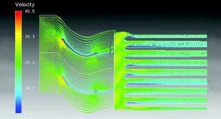
Flow analysis were then performed for a full fan and cooling fins which is shown in Fig.1, to ensure that the desired air flow speed on the fins is obtained. The impeller exit flow condition was of particular interest. A uniform flow aligned with the fins was highly desirable so that there no flow separation in the air passage through the cooling fans which could cause hot spots.


Fig.2: Velocity contours in the fins.


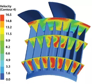
Figures 2 & 3 presents velocity contours in the fins which shows a relatively uniform flow is delivered by the impeller through the cooling fins.


Fig.3: Velocity contours showing a uniform flow through the cooling fins.


Get the Latest Updates Direct to Your Inbox