
Founded in Denmark in 1945, Grundfos now has an annual turnover of £2.6 billion and has an annual production of more than 16 million pump units, making Grundfos one of the world’s leading pump manufacturers. Circulator pumps for heating and air-conditioning as well as other centrifugal pumps for the industry, water supply, sewage and dosing are the main products. Today Grundfos is the world’s largest manufacturer of circulators, covering approximately 50% of the world market of these pumps. The Grundfos Group is represented by more than 80 companies in more than 55 countries.
Grundfos has been a pioneer in utilizing computer aided engineering ( CAE) in their design, development and manufacturing process for pumps and motors. They have been using CAD since 1980 and first introduced CFD in 1992. In the past 10 years a new integrated CAE and design system based on using ANSYS/CFX for structural and fluid flow analysis and TURBOdesign 1 for hydrodynamic design has been used in Grundfos. Grundfos selected TURBOdesign1 as the hydraulic design system of choice because application of TURBOdesign1 resulted in significant improvement in efficiency and suction performance of various pump applications. Another important advantage was the possibilities that TURBOdesign1 and the inverse design based approach provided for rapid and accurate 3D automatic optimization.
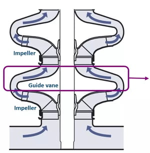
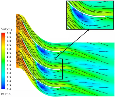
The flow field in many conventionally designed guide vanes of the type used for multistage pump such as that shown in Fig. 1 suffers from a corner separation, that not only affects the stage performance but also has an adverse effect on the follow on stage. In Fig. 2 the flow prediction in the baseline guidevane is shown where a corner separation can be observed on the hub/suction surface corner.
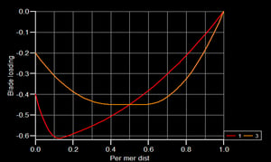
The guidevane was redesigned by using afore-loaded distribution at the hub and aft-loaded distribution at the shroud, meaning the corner separation could be reduced substantially. The loading distribution used is shown in Fig. 3. This type of loading removes the positive pressure gradient at the hub and also results in secondary flows from shroud to hub which move the low momentum fluid away from the endwall. The resulting flow prediction in the guidevane designed by TURBOdesign1 is shown in Fig. 4.
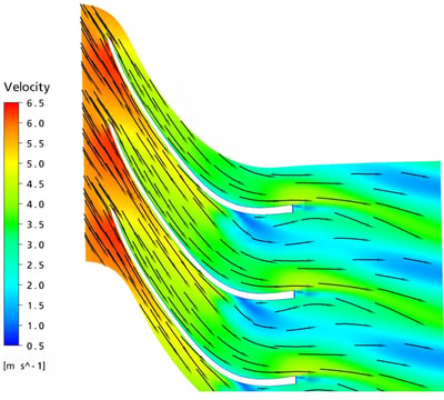
This shows substantial reduction in the corner separation. In Fig. 5 the predicted stage performance of the stage with the new redesign guidevane is compared with the baseline. There is significant increase in efficiency across the flow range and peak efficiency improves by 4% point.
One of the main issues facing pump manufacturers is the requirement to meet emission regulations such as EU’s ECOdesign directive. These regulations consider the life cycle emission from the pump and hence mean that the design of the pump must be done in such a way that considers performance at multiple operating points. In order to meet these requirements efficiently, Grundfos has developed an automatic optimization strategy based on Design of Experiments, Surrogate modelling using Kriging and then running optimization such as Multi-objective genetic algorithm on the surrogate model. Fig. 6 shows the schematic of this system. In this system the main dimensioning is done by using an inhouse meanline code and 3D geometry generation is done by using TURBOdesign1.
.webp?width=500&name=AnyConv.com__Optimization%20(1).webp)
Each geometry of impeller in the DOE table is meshed automatically for CFD. This is then followed by CFD computation at multiple operating points and post processing of relevant information such as efficiency, head and power at various points. In addition, a measure of production fitness of the impeller geometry for a given manufacturing method is computed. Typical runs involve about 40 impeller configurations generated by TURBOdesign1. The resulting surrogate models are generally very accurate. This accuracy is only possible because TURBOdesign1 can maintain the Euler head for the different geometries in the DOE table. Furthermore, with the inverse design approach a large design space can be covered by just a few design parameters related to blade loading.
.webp?width=400&name=AnyConv.com__grundfos-graph%20(1).webp)
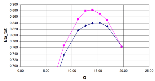
The result of the application of this approach has led to substantial improvement in product performance with reduced design cost and lead time. It has resulted in improving hydraulic efficiency of the pump by 1-2%, while extending the maximum efficiency level over a wider range of flow rates, see Fig. 7.